Basic Deployment
The basic procedure for deploying a VPC is as follows:
- Create an L2 public network and attach it to the corresponding cluster.
- Create an L3 public network.
- Create an L2 management network and attach it to the corresponding cluster.
- Create an L3 management network to communicate with physical resources, such as hosts, primary storages, and backup storages.
- Add a vRouter image.
- Create a vRouter offering.
- Create a VPC vRouter from the vRouter offering you created in the preceding step.
- Create an L2 private network and attach it to the corresponding cluster. This L2 private network is used to create an L3 VPC network (VPC Network-1).
- Specify a VPC vRouter to create an L3 VPC network (VPC Network-1). Note that the IP ranges cannot overlap.
- Create an L2 private network and attach it to the corresponding cluster. This L2 private network is used to create an L3 VPC network (VPC Network-2).
- Specify a VPC vRouter to create an L3 VPC network (VPC Network-2). Note that the IP ranges cannot overlap.
- Use VPC Network-1 and VPC Network-2 to create VM-1 and VM-2, respectively.
- Test the interoperability between VPC Network-1 and VPC Network-2.
Assume that your environment is as follows:
- Public Network
Table 1. Configuration Information Public Network Configuration Information NIC em01 VLAN ID No VLAN IP range 10.108.10.100~10.108.10.200 Netmask 255.0.0.0 Gateway 10.0.0.1 DHCP IP 10.108.10.101 - Management Network
Table 2. Configuration Information Management Network Configuration Information NIC em02 VLAN ID No VLAN IP range 192.168.29.10~192.168.29.20 Netmask 255.255.255.0 Gateway 192.168.29.1  Note:
Note:
- For security and stability reasons, we recommend that you deploy an independent management network and separate it from the public networks.
- The management network we mentioned here is the same as that in ZStack Private Cloud. That is, the management network is the network used to manage hosts, primary storages, and backup storages. If a management network was created before, you can use it directly.
- VPC Network-1
Table 3. Configuration Information Private Network Configuration Information NIC em01 VLAN ID 2800 IP CIDR 192.168.10.0/24 Gateway 192.168.10.1 DHCP IP 192.168.10.2 - VPC Network-2
Table 4. Configuration Information Private Network Configuration Information NIC em01 VLAN ID 2900 IP CIDR 192.168.11.0/24 Gateway 192.168.11.1 DHCP IP 192.168.11.2
To create a VPC in the Cloud, follow these steps:
-
Create an L2 public network in the ZStack Private
Cloud UI.
In the navigation pane of the ZStack Private Cloud UI, choose . On the L2 Network page, click Create L2 Network. On the displayed Create L2 Network page, set the following parameters according to the Table 1:
- Name: Enter a name for the L2 public network.
- Description: Optional. Enter a description for the L2 public network.
- Type: Select L2NoVlanNetwork.
- Physical NIC: Enter em01.
- Enable SR-IOV: Choose whether to enable SR-IOV. Here, leave this checkbox unselected.
- Cluster: Select a cluster, for example, Cluster-1.
Click OK. Then, an L2 public network will be created, as shown in Figure 1.Figure 1. Create L2 Network 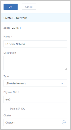
-
Create an L3 public network in the ZStack Private
Cloud UI.
In the navigation pane of the ZStack Private Cloud UI, choose . On the Public Network page, click Create Public Network. On the displayed Create Public Network page, set the following parameters according to the Table 1:
- Name: Enter a name for the L3 public network.
- Description: Optional. Enter a description for the L3 public network.
- L2 Network: Select the L2 public network you created in the preceding step.
- Stop DHCP server: Choose whether
to enable the DHCP service.Note:
- By default, this checkbox is not selected, indicating that the DHCP service is enabled, and IP addresses will be automatically allocated to VM instances. In this case, you can customize a DHCP IP address, or let the system randomly specify a DHCP IP address.
- If selected, the DHCP service will be disabled, indicating that VM instances that use this network cannot obtain IP addresses automatically, and need to be configured manually with IP addresses. In this case, you cannot customize the DHCP IP address. In addition, the system cannot randomly specify a DHCP IP address.
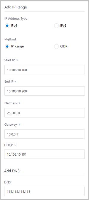
- Add IP Range: Select the IPv4 IP address type
and the IP range method.Note: ZStack supports both
IPv4 and IPv6. You can choose to add an IP range or a CIDR. This
tutorial takes the IPv4 IP address and IP range method as
examples.
- Start IP: Enter a start IP address, for example, 10.108.10.100.
- End IP: Enter an end IP address, for example, 10.108.10.200.
- Netmask: Enter a netmask, for example, 255.0.0.0.
- Gateway: Enter a gateway, for example, 10.0.0.1.
- DHCP IP: Optional. Set a DHCP IP address as
needed.Note:
- If you create an L3 network and enable the DHCP service for the first time, or if you add the first IP range for the L3 network of the enabled DHCP service, you can customize the DHCP IP address.
- If the L3 network has a DHCP IP address, you cannot customize the DHCP IP address when you add an IP range.
- The DHCP IP address can be included or excluded on the added IP range. However, the DHCP IP address must be within the CIDR to which the added IP range belongs, and must not be occupied.
- The IP range specified within the start IP address and end IP address cannot contain IP addresses of the link-local address (169.254.0.0/16).
- If not specified, the system will randomly specify an IP address within the IP range that you added.
- DNS: Optional. Set a DNS, for example, 114.114.114.114.
Click OK. Then, an L3 public network will be created, as shown in Figure 2.Figure 2. Create L3 Public Network 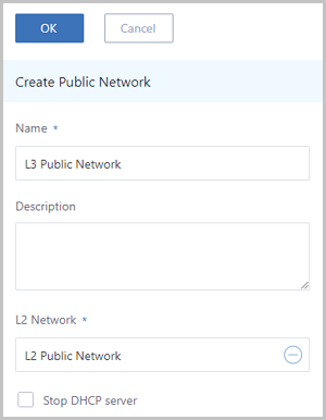
-
Create an L2 management network in the ZStack Private
Cloud UI.
In the navigation pane of the ZStack Private Cloud UI, choose . On the L2 Network page, click Create L2 Network. On the displayed Create L2 Network page, set the following parameters according to the Table 2:
- Name: Enter a name for the L2 management network.
- Description: Optional. Enter a description for the L2 management network.
- Type: Select L2NoVlanNetwork.
- Physical NIC: Enter em02.
- Enable SR-IOV: Choose whether to enable SR-IOV. Here, leave this checkbox unselected.
- Cluster: Select a cluster, for example, Cluster-1.
Click OK. Then, an L2 management network will be created, as shown in Figure 3.Figure 3. Create L2 Management Network 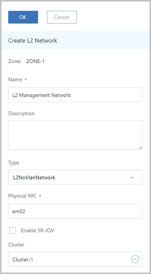
-
Create an L3 management network in the ZStack Private
Cloud UI.
In the navigation pane of the ZStack Private Cloud UI, choose . On the System Network page, click Create System Network. On the displayed Create System Network page, set the following parameters according to the Table 2:
- Name: Enter a name for the L3 management network.
- Description: Optional. Enter a description for the L3 management network.
- L2 Network: Select the L2 management network you created in the preceding step.
- Add IP Range: Select the IP range method.
- Start IP: Enter a start IP address, for example, 192.168.29.10.
- End IP: Enter an end IP address, for example, 192.168.29.20.
- Netmask: Enter a netmask, for example, 255.255.255.0.
- Gateway: Enter a gateway, for example, 192.168.29.1.
Click OK. Then, an L3 management network will be created, as shown in Figure 4.Figure 4. Create L3 Management Network 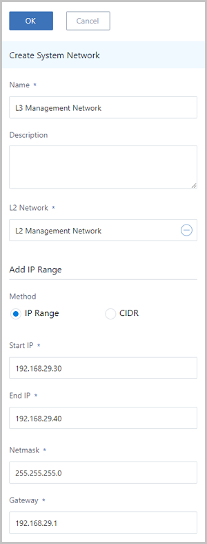
-
Add a vRouter image.
In the navigation pane of the ZStack Private Cloud UI, choose . On the vRouter Image page, click Add vRouter Image. On the displayed Add vRouter Image page, set the following parameters:
- Name: Enter a name for the vRouter image.
- Description: Optional. Enter a description for the vRouter image.
- Backup Storage: Select a backup storage to store the vRouter image, for example, BS-1.
- Image URL: Enter a local URL or upload a local
file.
- URL: Enter the path that can download the
vRouter image.Note:
ZStack provides you with dedicated vRouter images. Download the latest vRouter images from ZStack Official Website.
- File name: zstack-vRouter-3.10.0.qcow2
- Download address: Click ZStack Official Website.
- Local file: Upload a vRouter image file that
can directly be accessed by the current browser.Note:
- vRouter images can be uploaded to an ImageStore or Ceph backup storage.
- A local browser will serve as a transmission relay used for uploading vRouter images. Make sure that you do not refresh or stop the current browser, and do not stop your management node. Or otherwise, you will fail to add a vRouter image.
- URL: Enter the path that can download the
vRouter image.
Click OK. Then, a vRouter image will be added, as shown in Add vRouter Image.Figure 5. Add vRouter Image 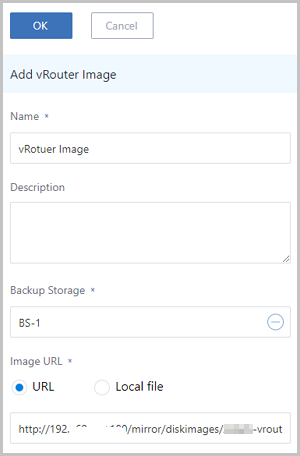
-
Create a vRouter offering.
In the navigation pane of the ZStack Private Cloud UI, choose . On the vRouter Offering page, click Create vRouter Offering. On the displayed Create vRouter Offering page, set the following parameters:
- Name: Enter a name for the vRouter offering.
- Description: Optional. Enter a description for the vRouter offering.
- CPU: Set the CPU count for the vRouter offering. In an actual production environment, we recommend that the CPU count must be greater than 8.
- Memory: Set the memory size for the vRouter offering. Unit: M | G | T. In an actual production environment, we recommend that the memory size must be greater than 8 G.
- Image: Select the vRouter image that you
added.Note: If the L3 public network in the vRouter offering has an IP
range with the IPv6 type, when you create a VPC vRouter, you must use
the vRouter image of version 3.10.0 and later.
- Management Network: Select the L3 management network that you created from the network list.
- L3 Network: Select an L3 network that you created
from the network list, including public network and flat network.
- If the L3 network is a public network, the vRouter or VPC vRouter created from this vRouter offering can provide various network services for vRouter networks and VPC networks.
- If the L3 network is a public network, the vRouter created from this vRouter offering can provide load balancing network services for flat networks.
- If the L3 network is a flat network, the vRouter created from this vRouter offering can provide load balancing network services for flat networks.
Click OK. Then, a vRouter offering will be created, as shown in Create vRouter Offering.Figure 6. Create vRouter Offering 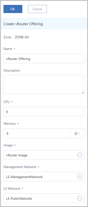
-
Create a VPC vRouter from the vRouter offering you created in the preceding
step.
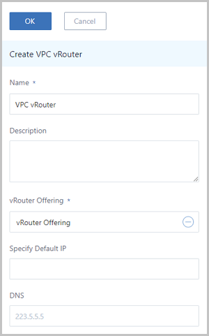
In the navigation pane of the ZStack Private Cloud UI, choose . On the VPC vRouter page, click Create VPC vRouter. On the displayed Create VPC vRouter page, set the following parameters:
- Name: Enter a name for the VPC vRouter.
- Description: Optional. Enter a description for the VPC vRouter.
- vRouter Offering: Select the vRouter offering you created in the preceding step.
- Specify Default IP: Optional. Specify a public IP address as the default IP address of the VPC vRouter.
- DNS: Optional. Set the DNS for the VPC vRouter. Default value: 223.5.5.5.
-
Create an L2 private network in the ZStack Private
Cloud UI. This L2 private
network is used to create an L3 VPC network (VPC Network-1).
In the navigation pane of the ZStack Private Cloud UI, choose . On the L2 Network page, click Create L2 Network. On the displayed Create L2 Network page, set the following parameters according to the Table 3:
- Name: Enter a name for the L2 private network.
- Description: Optional. Enter a description for the L2 private network.
- Type: Select L2VlanNetwork.
- VLAN ID: Enter 2800.
- Physical NIC: Enter em01.
- Enable SR-IOV: Choose whether to enable SR-IOV. Here, leave this checkbox unselected.
- Cluster: Select a cluster, for example, Cluster-1.
Click OK. Then, an L2 private network will be created, as shown in Figure 8.Figure 8. Create L2 Private Network 
-
Specify a VPC vRouter in the ZStack Private
Cloud to create an L3 VPC
network (VPC Network-1).
In the navigation pane of the ZStack Private Cloud UI, choose . On the VPC Network page, click Create VPC Network. On the displayed Create VPC Network page, set the following parameters according to the Table 3:
- Name: Enter a name for the VPC network, such as VPC Network-1.
- Description: Optional. Enter a description for the VPC network.
- L2 Network: Select the L2 private network you created in the preceding step.
- VPC vRouter: Optional. Specify a VPC vRouter directly, or attach a VPC vRouter after you create a VPC network.
- Stop DHCP server: Choose whether
to enable the DHCP service.Note:
- By default, this checkbox is not selected, indicating that the DHCP service is enabled, and IP addresses will be automatically allocated to VM instances. In this case, you can customize a DHCP IP address, or let the system randomly specify a DHCP IP address.
- If selected, the DHCP service will be disabled, indicating that VM instances that use this network cannot obtain IP addresses automatically, and need to be configured manually with IP addresses. In this case, you cannot customize the DHCP IP address. In addition, the system cannot randomly specify a DHCP IP address.
- Add IP Range: Select the CIDR method.
- CIDR: Enter a CIDR, for example,
192.168.10.0/24.Note: The IP ranges cannot be
overlapped.
- Gateway: Enter a gateway, for example, 192.168.10.1.
- DHCP IP: Optional. Set a DHCP IP address as
needed.Note:
- If you create an L3 network and enable the DHCP service for the first time, or if you add the first network range for the L3 network of the enabled DHCP service, you can customize the DHCP IP address.
- If the L3 network has a DHCP IP address, you cannot customize the DHCP IP address when you add the IP range.
- The DHCP IP address can be included or excluded on the IP range that you added. However, the DHCP IP address must not be in conflict with the current CIDR.
- If not specified, the system will randomly specify an IP address within the added IP range.
- The first IP address in a CIDR is deemed as a gateway by default, and cannot serve as a DHCP IP address.
-
Create an L2 private network in the ZStack Private
Cloud UI. This L2 private
network is used to create an L3 VPC network (VPC Network-2).
In the navigation pane of the ZStack Private Cloud UI, choose . On the L2 Network page, click Create L2 Network. On the displayed Create L2 Network page, set the following parameters according to the Table 4:
- Name: Enter a name for the L2 private network.
- Description: Optional. Enter a description for the L2 private network.
- Type: Select L2VlanNetwork.
- VLAN ID: Enter 2900.
- Physical NIC: Enter em01.
- Enable SR-IOV: Choose whether to enable
SR-IOV.
- By default, this checkbox is not selected, indicating that SR-IOV is not enabled. In this case, SR-IOV cannot be enabled for the L3 network corresponding to the L2 network.
- If selected, SR-IOV is enabled. You can also enable SR-IOV for the L3 network corresponding to the L2 network. In this case, make sure that VF NICs are generated from physical NICs used by the L2 network.
- Cluster: Select a cluster, for example, Cluster-1.
Click OK. Then, an L2 private network will be created, as shown in Figure 10.Figure 10. Create L2 Private Network 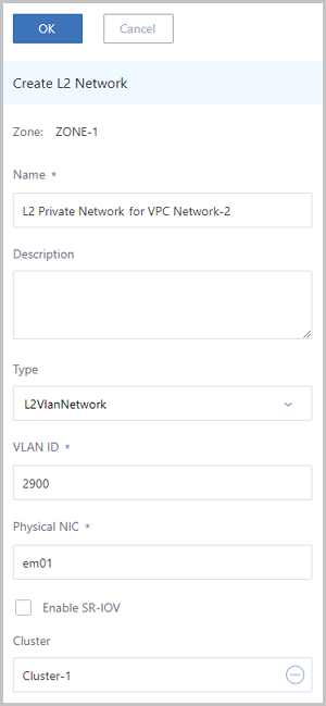
-
Specify a VPC vRouter in the ZStack Private
Cloud to create an L3 VPC
network (VPC Network-2).
In the navigation pane of the ZStack Private Cloud UI, choose . On the VPC Network page, click Create VPC Network. On the displayed Create VPC Network page, set the following parameters according to the Table 4:
- Name: Enter a name for the VPC network, such as VPC Network-2.
- Description: Optional. Enter a description for the for the VPC network.
- L2 Network: Select the L2 private network you created in the preceding step.
- VPC vRouter: Optional. Specify a VPC vRouter directly, or attach a VPC vRouter after you create a VPC network.
- Stop DHCP server: Choose whether
to enable the DHCP service.Note:
- By default, this checkbox is not selected, indicating that the DHCP service is enabled, and IP addresses will be automatically allocated to VM instances. In this case, you can customize a DHCP IP address, or let the system randomly specify a DHCP IP address.
- If selected, the DHCP service will be disabled, indicating that VM instances that use this network cannot obtain IP addresses automatically, and need to be configured manually with IP addresses. In this case, you cannot customize the DHCP IP address. In addition, the system cannot randomly specify a DHCP IP address.
- Add IP Range: Select the CIDR method.
- CIDR: Enter a CIDR, for example,
192.168.11.0/24.Note: The IP ranges cannot be
overlapped.
- Gateway: Enter a gateway, for example, 192.168.11.1.
- DHCP IP: Optional. Set a DHCP IP address as
needed.Note:
- If you create an L3 network and enable the DHCP service for the first time, or if you add the first network range for the L3 network of the enabled DHCP service, you can customize the DHCP IP address.
- If the L3 network has a DHCP IP address, you cannot customize the DHCP IP address when you add the IP range.
- The DHCP IP address can be included or excluded on the IP range that you added. However, the DHCP IP address must not be in conflict with the current CIDR.
- If not specified, the system will randomly specify an IP address within the added IP range.
- The first IP address in a CIDR is deemed as a gateway by default, and cannot serve as a DHCP IP address.
Click OK. Then, VPC Network-2 will be created, as shown in Figure 11.Figure 11. Create VPC Network-2 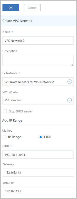
-
Use VPC Network-1 to create VM-1, and use VPC Network-2 to create VM-2.
-
Use VPC Network-1 to create VM-1.
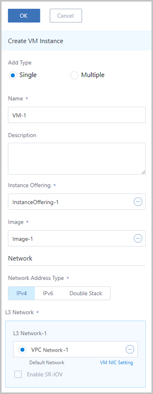
In the navigation pane of the ZStack Private Cloud UI, choose . On the VM Instance page, click Create VM Instance. On the displayed Create VM Instance page, set the following parameters:
- Add Type: Select
Single. - Name: Enter VM-1.
- Description: Optional. Enter a description for VM-1.
- Instance Offering: Select an instance offering you created before.
- Image: Select a VM image you added before.
- Network: Click on the IPv4 tab and select VPC Network-1.
- Add Type: Select
-
Use VPC Network-1 to create VM-1.
- Test the interoperability between VPC Network-1 and VPC Network-2.

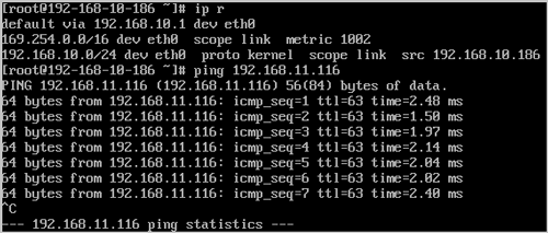
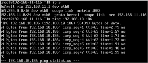
So far, we introduced the basic deployment of a VPC.